- What is Oil Sludge Lagoon?
Sludge lagoon is an unwanted oil or other liquid waste generated in a process of oil extraction, transfer, refining etc. Sludge lagoon is a serious source of environment pollution and must be a subject of remediation.
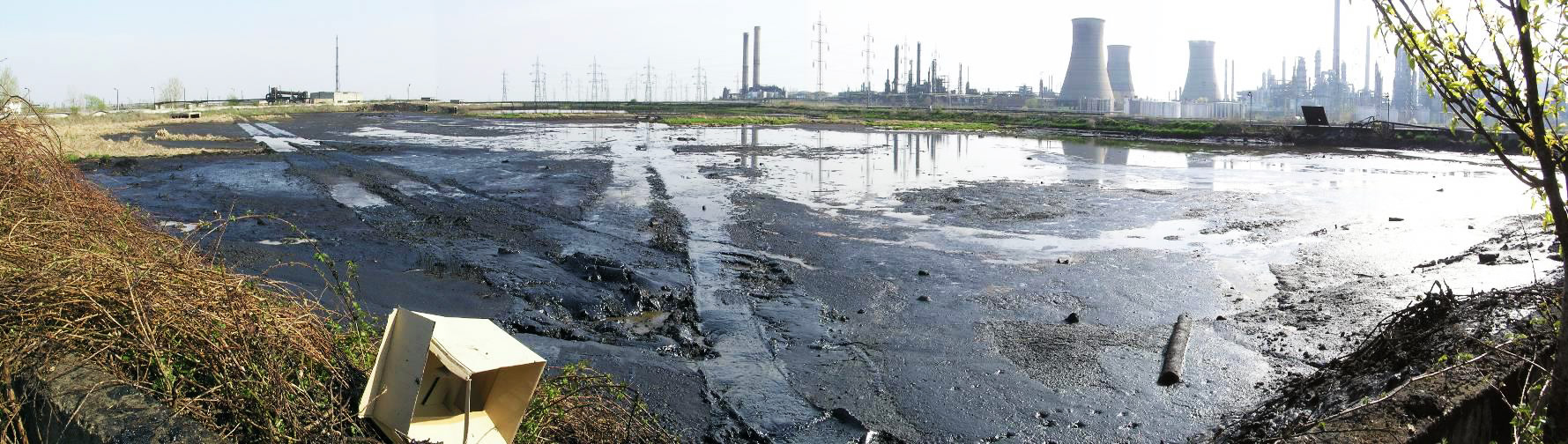
- Remediation of a Sludge Lagoon.
A first standard step prior to the actual clean-up is to collect data for a creation of a feasibility study and an implementation clean-up design. A pilot scale test of the proposed design should be performed. For that available is an extensive lab and technological set-up developed for conducting of a sludge treatability tests. Some examples are shown below:
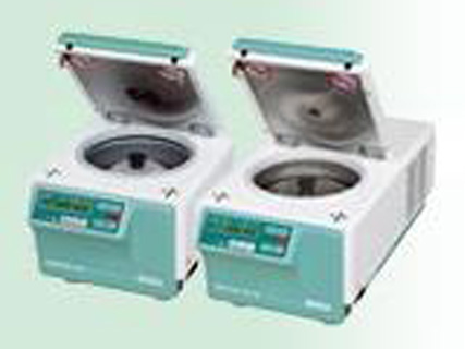
Laboratory centrifuges
– oil sludge sentrifugation tests
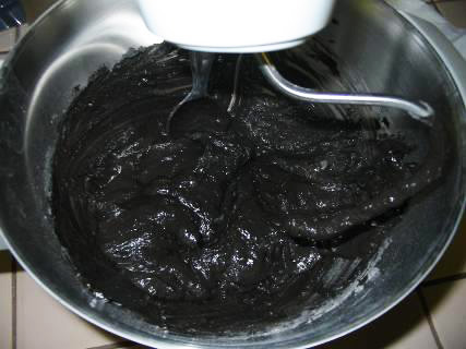
Laboratory mixer
– oil sludge S/S tests and AF production tests
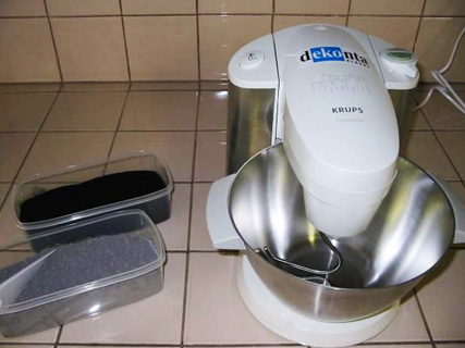
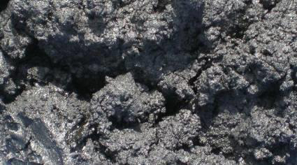
Mixer
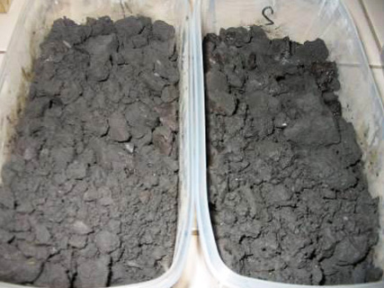
Solidified material
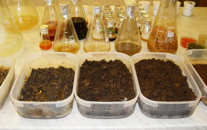
Equipment for laboratory bioremediation tests
– testing biotechnological treatability of oil sludge, contaminated soil and other waste from the lagoon site
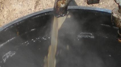
There are two steps of oil lagoon remediation: pumping off a liquid deposit followed by excavation and removal / treatment of the remaining solid part of pollution. The pumped off and solid waste are to be sorted out by”
- Centrifugal separation
- Production of oil waste derived alternative fuel
- Burning in a rotary kiln
The site cleared of its deposit is finally remediated by one of the classic remediation methods such as the ones mentioned at
- Typical Activities to Be Performed Immediately Prior and During Sludge Lagoon Remediation Exercise.
1. Investigation of oil sludge lagoon site
- Quantification of waste deposited in the lagoon
- Determination of deposited waste chemical-physical properties
- Assessment of crucial waste types distribution inside the lagoon
- Identification of soil / groundwater contamination at the lagoon site
2. Public health and environmental risk assessment study
- Identification of risk scenarios resulting from the real or potential negative impact of oil waste deposited in the lagoon on public health or on the environment
- Determination of maximum acceptable soil and groundwater contamination levels at the lagoon site („Target limits“)
3. Feasibility study on the lagoon site remediation
- Selection of the most suitable approach to the lagoon site remediation
- Selection of the most suitable re
4. Implementation design
- Detailed technical design of the selected remediation approach and method implementation (must respect the site-specific conditions, applicable legal requirements and technical standards, client´s requirements etc.)
5. Permitting
- Approval of elaborated Implementation design
- Obtaining all permits, licences and approvals necessary for implementation of the designed activities in accordance with applicable legal requirements and site-specific decisions of local authorities
6. Acquiring, mobilization and installation of technological equipment
- Erection of technological equipment necessary for the lagoon site remediation in accordance with the approved Implementation design
7. Remediation
- Achievement of all goals and target limits specified in the approved Implementation design
- Handover of the remediated site to the client
8. Post-remediation monitoring
- Verification of long-term sustainable outputs of the remediation project
Standard scheme of lagoon remediation activity
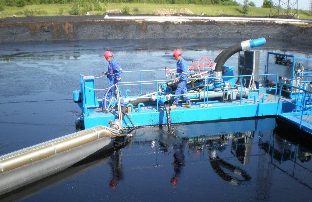
While smaller sludge lagoons are pumped off by stationary pumps, the larger ones may be pumped by using the floating pumping stations
- Separation Centrifuges.
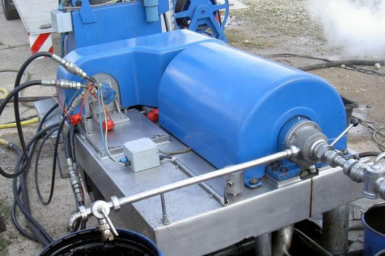
- For larger oil lagoons clean-up projects a separation centrifuge as the one shown below may be utilized
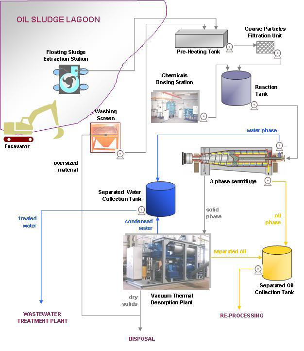
Oil sludge separation on 3-phase centrifuges
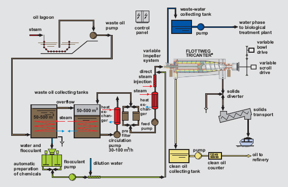
Patented Flotweg Tricanters (3-phase centrifuges) are used for separation of pumped oil sludge into 3 products: oil, water and solids. Before centrifugation, the sludge is pre-treated so that optimum separation is achieved.
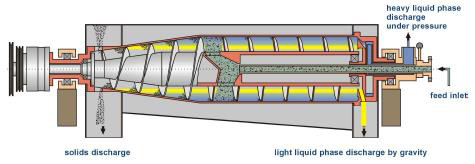
Schemat of a 3 - Phase Centrifuge
Oil
Water
Solid
A typical scheme of the centrifugation process is shown at the below diagram: